


What Sensors Does Molding Equipment Need for Predictive Maintenance?
What Sensors Does Molding Equipment Need for Predictive Maintenance?
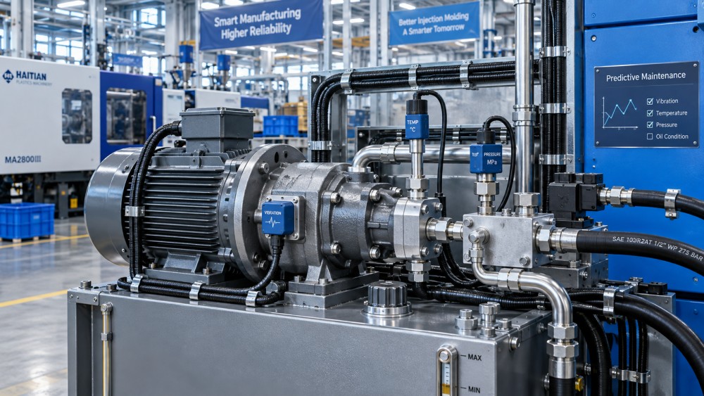
Unplanned downtime in injection molding, die-casting, extrusion, and rubber processing can disrupt production, increase scrap, and strain maintenance budgets. Which sensors are needed for predictive maintenance on molding equipment? The answer depends on the machine’s critical components and failure modes—not simply the number of sensors installed. Vibration, temperature, pressure, motor current, and oil-condition monitoring can reveal early warning signs when interpreted alongside operating conditions.
For many plants, the sensible starting point is a small monitoring package around the main drive, hydraulic power unit, or extrusion gearbox. But an all-electric injection molding machine and a hydraulic die-casting cell need different priorities. The useful question is: Which developing fault could stop this machine, and what measurable signal would change before it does?
Start with the failure, not the sensor catalog
Review breakdown records, maintenance notes, and recurring quality problems before specifying hardware. Separate mechanical deterioration from process instability. A worn gearbox bearing, a sticking hydraulic valve, and a moisture-sensitive resin can all disturb production, but they will not respond to the same monitoring strategy.
Also check what the machine already measures. Controllers may expose drive current, torque estimates, actual position, hydraulic pressure, barrel temperature, and cycle timing. These signals can provide a useful baseline without additional instruments. Their limitations matter, though: a slowly updated controller value may reveal gradual load changes while missing a short pressure transient or bearing vibration.
Prioritize components with significant downtime consequences, difficult spare-part availability, or detectable deterioration. Sensors cannot reliably predict every sudden failure. A cable damaged during mold changing, for example, may offer little warning. Condition monitoring should support preventive tasks and inspections, not replace them wholesale.
The core sensors—and what each one actually tells you
Vibration sensors for bearings, gearboxes, and rotating drives
Accelerometers are often the first choice for monitoring extrusion gearboxes, hydraulic pump bearings, motors, and rubber-processing drive trains. They can expose changes associated with imbalance, looseness, misalignment, and bearing or gear damage. Diagnosis usually requires frequency information and sometimes envelope analysis; a single overall vibration value rarely identifies the fault.
Placement is decisive. Mount sensors rigidly on suitable bearing housings or structural locations close to the load path. A convenient sheet-metal cover can produce a misleading signal. On reciprocating molding equipment, mold closure and injection create normal shocks, so compare vibration during equivalent cycle phases rather than treating every peak as damage.
Variable-speed drives require speed context. If shaft speed changes, relevant vibration frequencies move too. Record speed alongside vibration, and choose sensor bandwidth and acquisition settings for the faults being investigated. Wireless units may suit periodic screening, but verify whether their sampling schedule captures the operating state you need.
Temperature sensors for thermal drift and cooling problems
RTDs, thermocouples, and suitable surface probes can track bearing housings, hydraulic oil, motors, cooling circuits, and heating zones. Rising temperature can support evidence of lubrication trouble, excessive load, or restricted cooling. It is not a diagnosis by itself: ambient conditions, production rate, and warm-up behavior also affect readings.
For barrel heaters, compare temperature behavior with heater demand or current. A zone taking longer to recover under a comparable recipe may justify checking the heater, wiring, sensor installation, or material load. A temperature reading that remains near setpoint does not necessarily prove every heater is healthy; adjacent zones can partially mask a problem.
Pressure and flow sensors for hydraulic and cooling systems
Hydraulic machines benefit from pressure measurements at locations chosen for a specific question: pump delivery, actuator response, or filter differential pressure. Pressure traces synchronized with machine commands can help reveal slower response, leakage, or unstable control. Comparing pressure with oil temperature, valve state, and cycle time helps separate deterioration from viscosity or recipe changes.
Cooling-water flow deserves attention when blocked passages or interrupted circulation repeatedly disrupt production. Supply pressure alone cannot confirm adequate flow through an individual circuit. Flow measurement combined with inlet and outlet temperatures provides better context, although changing mold heat loads must still be considered.
Hydraulic pressure, nozzle pressure, and cavity pressure are not interchangeable. Cavity sensors are valuable for process consistency and quality monitoring, but changes in their traces can reflect material or tooling conditions rather than machine wear.
Motor current and torque for changing mechanical load
Current transducers or existing drive telemetry can identify changes in load on screw drives, pumps, clamp systems, and auxiliary equipment. On all-electric molding machines, torque and position signals may be particularly useful for observing increasing resistance or unusual motion behavior.
Interpret these signals against the recipe. Higher screw torque could reflect a resin change, colder material, increased throughput, or mechanical resistance. Drive-reported torque is generally an estimate, not a direct shaft measurement. Use it for consistent trending, and confirm suspicious changes with another signal or inspection before scheduling intrusive work.
Oil-condition sensors for lubrication and hydraulic health
Depending on the system, online instruments can monitor particle contamination, moisture, or oil-property changes. Wear-debris monitoring may be valuable for critical gearboxes, while hydraulic cleanliness monitoring can help identify contamination risks to pumps and valves.
Installation conditions affect reliability. Air bubbles, sample flow, oil temperature, and measurement location can influence results. Select instruments compatible with the fluid and operating conditions, and retain laboratory analysis where detailed chemistry or wear-metal identification is needed. An online oil sensor does not replace a complete lubricant assessment.
Choose a different starting package for each machine
A practical initial package should follow the dominant failure risks, not a universal checklist. The combinations below are starting points to validate against service history and machine design.
- Hydraulic injection molding: pump vibration, oil temperature, and hydraulic pressure, with contamination monitoring where oil-related failures justify it.
- All-electric injection molding: existing servo current, torque, position, and following-error data; add vibration or temperature sensing around vulnerable rotating components.
- Die-casting: hydraulic response and oil health where applicable, plus cooling-flow monitoring. Protect instruments and cables from heat, spray, and mechanical impact.
- Extrusion: gearbox vibration and temperature, lubricant monitoring for critical drives, and screw-drive load. Use melt pressure as process context, not standalone proof of wear.
- Rubber processing: drive-train condition and thermal behavior, interpreted by compound and batch stage because load changes can be substantial.
Position, displacement, or strain sensing may be justified when clamp behavior, platen movement, or load balance is the concern. These are targeted additions. Installation and interpretation generally require machine-specific engineering, particularly around highly loaded structures.
Connect the signals without losing their meaning
An IIoT gateway should collect more than sensor values. Useful context includes timestamps, cycle phase, machine state, recipe, material designation, speed, and recent maintenance events. Without that context, a perfectly normal change from one mold or compound to another can trigger an unnecessary alarm.
Match acquisition speed to the phenomenon. Slow temperature trends and high-frequency bearing analysis have different requirements. High-rate vibration data may need local processing, with selected waveforms and diagnostic features retained instead of transmitting everything continuously. Confirm synchronization, buffering during network outages, and access to raw data before committing to a platform.
Use OEM-supported interfaces where available and avoid interfering with machine controls. Monitoring should normally remain separate from safety functions. Hydraulic connections and electrical measurements require qualified installation; sensor retrofits must not compromise guarding, pressure ratings, or service access.
Turn a warning into a maintenance decision
Build baselines while equipment condition is understood, covering normal recipes and operating states. Do not automatically label the first collected data “healthy.” A machine can already have a worn bearing or restricted cooler when monitoring begins.
Then define a response to each warning. If gearbox vibration rises under comparable speed and load, check whether the change persists, whether temperature or debris readings support it, and whether inspection is warranted. A persistent, corroborated change is more actionable than an isolated threshold crossing.
Record what technicians find and link it back to the alert. This helps distinguish useful warnings from nuisance alarms and improves future thresholds. Trend monitoring becomes predictive maintenance when the evidence informs an intervention before functional failure. It does not automatically provide a reliable remaining-life estimate.
The connection between material behavior and equipment condition is central to GPM-Matrix’s coverage of molding technology and resource efficiency. A recycled feedstock change can alter torque and pressure without indicating deterioration. Conversely, a degrading drive or cooling circuit can destabilize an otherwise sound process. Evaluating both sides helps avoid unnecessary repairs and repeated scrap.
Start with one critical subsystem and a defined maintenance decision. Specify the suspected failure, sensor location, operating context, and confirmation method before buying hardware. If nobody can explain what action follows a warning, the next investment should be in the maintenance workflow—not another sensor.
Related News
- 00
0000-00
How to compare molding equipment for high-volume production - 00
0000-00
EU Tightens Food-Contact Recycled PET Import Controls and Adds Customs Code - 00
0000-00
How to size vulcanizing equipment for rubber hoses - 00
0000-00
Is natural rubber more price volatile than synthetic rubber? - 00
0000-00
EU Tightens Import Controls and Traceability for Food-Contact Recycled PET